Plate Load Test is a field test to determine the bearing capacity of the soil. It is most widely adopted method to evaluate the safe bearing capacity. The test essentially consists in loading a rigid plate at the foundation level, & determining the settlements to each load increment. The ultimate bearing capacity is then taken as the load at which the plate starts sinking at the rapid rate. It is based on the assumption that, the soil stratum is reasonably uniform down to the influences of stresses.
Bearing Plate: The bearing plate is either circular or square plate, made up of mild steel and less than 25mm thick and size varies from 300 to 750mm with grooved bottom. Alternatively, cast in situ or precast concrete blocks are used with depth not less than 2/3rd the width.
Test Pit: – The test pit is usually at the foundation level and generally width of the pit is equal to 5 times the width of plate. The plate is carefully levelled and cleaned. The bearing plate is placed over 5mm thick sand layer.
Loading Arrangement: – The loading to the test plate may be applied with the help of Hydraulic jack. The reaction of the hydraulic jack may be applied either one of the following methods:-
Gravity loading platform method.
Reaction truss method.
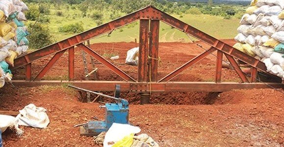
Gravity Loading Platform Method: – In Gravity loading method, a platform is constructed over a vertical column resting on the test plate and loading is done with the help of sand bags, stones or concrete blocks. When the load is applied to the plate it get sinks. The settlement is measured with the help of dial gauges. For square plates two dial gauges are used. The load is indicated on the pressure gauge of the hydraulic jack (refer to fig.1).
fig: 1
Reaction Truss Method: – In Reaction truss method the reaction of hydraulic jack is borne by reaction jack. The truss is held to the ground with soil anchors. These anchors are driven into the soil with the help of hammers. The reaction truss is usually made of steel truss. Guy ropes are used for the lateral stability of the truss. The use of the reaction truss is more popular now-a-days since this is simple, quick & less clumsy. Care should be taken that no support of loading platform should be located within a distance of 3.5 times the size of the test plate from its center.
Various operations involves in the test are as follows:
Setting of the plate: – The test plate shall be placed over a fine sand of maximum 5mm thickness. So that the center of the plate coincides with the center of the reaction girder/beam. Use plumb bob and spirit level to about eccentric loading. A minimum seating pressure of 70g/cm2 shall be applied and removed before starting the load test.
Load increments: – Apply load to soil in cumulative equal increments up to 1Kg/cm2 or one with of the estimate ultimate bearing capacity, whichever is less. The load is applied without any impact, fluctuation or eccentricity. The load is applied over the pressure gauge attached to the pumping unit of hydraulic jack away from the test plate.
Settlement and observation: – Settlement should be observed for each increment of load after an interval of 1, 2.25, 4, 6.25, 9, 16 and 25 minutes and thereafter at hourly intervals to the nearest 0.02mm. Where settlement does not reach 25mm, the test should be continued to at least two times the estimated design pressure.
Load settlement curve and ultimate bearing capacity: –
Load settlement curves are studied to arrive at ultimate bearing capacity of soil (refer to fig.2).
figure 2 : Load v/s Settlement
IS1888:1982 didn’t mention any factor of safety. For safe ultimate bearing capacity, normally sufficient to use 2 or 2.5 as factor safety of safety on the ultimate bearing capacity.
Assistant Professor Gaurav Sharma did his graduation (with Honours) from Rajasthan Technical University, Kota and post-graduation (with Honours ) from Maharana Pratap University of Agriculture and Technology , Udaipur. He has served as faculty member in various engineering colleges and universities recognized by AICTE and UGC. He has worked with SKP group of construction. Currently he is providing his services in a private engineering college as an Assistant Professor.


You must be logged in to post a comment.